
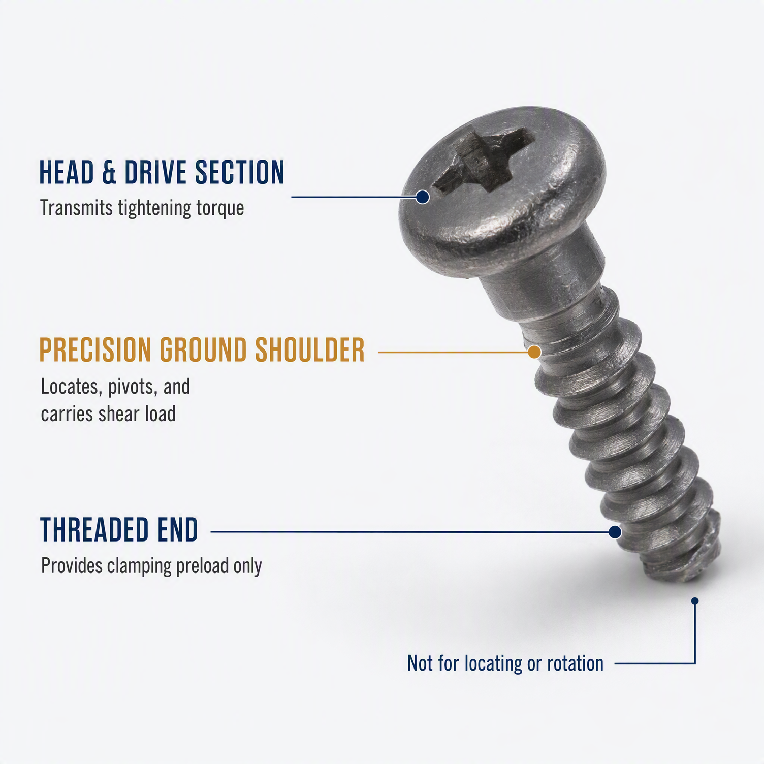
Shoulder screws separate positioning shoulder and clamping thread, widely used for automation equipment, instrument linkage, bearing pivot and limit‑spacing structure. Many engineers treat them as modified machine‑screws and only check thread parameters, ignoring shoulder‑related key specs. This produces various hidden risks after equipment delivery. Below are five typical mis‑application failures collected from OEM mechanical‑project feedback.
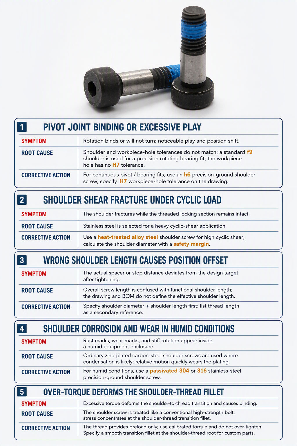
Failure 1: Pivot joint jamming or excessive clearance
Phenomenon: Rotating joint either locks and cannot turn smoothly, or generates obvious wobble & positioning offset.
Root‑cause: Mismatch between shoulder‑screw shoulder tolerance and workpiece bore‑hole tolerance. Using commercial‑grade f9 shoulder for precision rotating bearing fit, without matching H7 bore dimension.
Corrective action: For continuous‑rotation pivot / bearing fit, select h6 precision‑ground shoulder screws, and define matching H7 bore‑hole tolerance on mechanical drawing.
Failure 2: Shoulder section shear fracture under cyclic load
Phenomenon: Shoulder part breaks after repeated swing or cyclic shear load; thread‑clamping section remains intact.
Root‑cause: Applying stainless‑steel shoulder screws for heavy cyclic shear scenarios. Stainless steel delivers good corrosion resistance but limited shear strength.
Corrective action: For heavy‑shear cyclic‑motion structures, adopt heat‑treated alloy‑steel shoulder screws; reserve safety margin on shoulder‑diameter calculation.
Failure 3: Positioning offset caused by wrong shoulder length
Phenomenon: After tightening screw head, the spacing / limiting dimension deviates far from design target value.
Root‑cause: Confusing overall screw length with functional shoulder length. Engineers quote total screw length rather than effective shoulder length in drawing and BOM.
Corrective action: When specifying shoulder screws, mark shoulder diameter + shoulder length as primary dimension, thread length as secondary reference.
Failure 4: Corrosion & shoulder surface wear in damp workshop environment
Phenomenon: Shoulder surface gets rust and wear marks after short‑term operation in humid workshop; rotation becomes stiff.
Root‑cause: Using ordinary zinc‑plated carbon‑steel shoulder screws for damp or condensate‑prone equipment cabins. Plating layer on shoulder journal wears away quickly during relative movement.
Corrective action: Humid working‑condition: switch over to passivated 304 / 316 stainless‑steel precision ground shoulder screws.
Failure 5: Over‑tightening squeezes shoulder‑thread transition fillet
Phenomenon: Excessive torque deforms shoulder‑thread transition zone, causing rotation sticking.
Root‑cause: Treating shoulder screws as ordinary high‑torque bolts, applying over‑torque; stress concentrates at shoulder‑thread transition fillet.
Corrective action: Thread section only provides clamping pre‑load. Calibrate torque value, avoid over‑tightening; require smooth transition fillet at shoulder‑thread root on custom‑made parts.
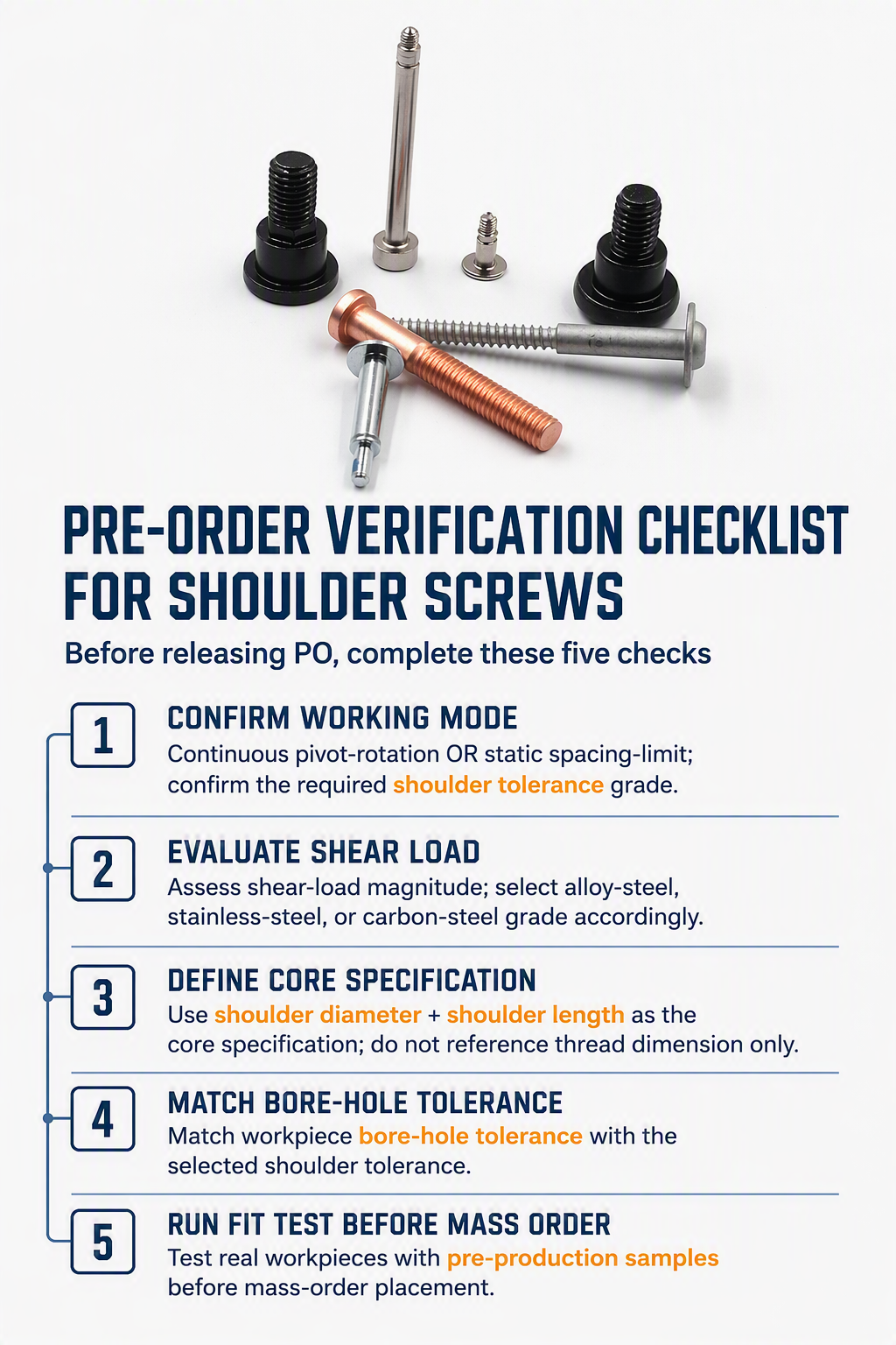
Pre‑order verification checklist for Shoulder Screws
Before releasing PO for shoulder screws, complete these five checks:
- Distinguish working mode: continuous pivot‑rotation OR static spacing‑limit, confirm required shoulder tolerance grade.
- Evaluate shear‑load magnitude, select corresponding material grade (alloy‑steel / stainless‑steel / carbon‑steel).
- Take shoulder diameter & shoulder length as core specification, do not only reference thread dimension.
- Match workpiece bore‑hole tolerance with shoulder tolerance.
- Run real‑workpiece fit test with pre‑production samples before mass‑order placement.
Final summary
The shoulder section, not the thread, defines core performance of shoulder screws. Many field‑failures origin from ignoring shoulder‑relevant parameters. In mechanical‑design phase, clarify rotation requirement, shear‑load and environment condition, communicate full dimension requirements with fastener suppliers, to prevent avoidable equipment defects.
Post time: Sep-03-2026