
Many design teams treat shoulder screws as simple variant bolts. In fact, the shoulder shank instead of the thread carries most mechanical loads. Ignoring shoulder‑related parameters will trigger hidden risks after equipment ships out. Summarized below are four specification mis‑steps collected from finished OEM mechanical projects.
Pitfall 1: Confusing total screw length with functional shoulder length
Phenomenon: After tightening the head, actual spacing or stop dimension deviates largely from drawing target value.
Root cause: Engineers fill overall screw length on BOM and drawings while ignoring effective shoulder length. Same overall length does not guarantee identical spacer dimension. Thread‑section length variation will change final assembled spacing result.
Corrective suggestion: When specifying shoulder screws, mark shoulder diameter and shoulder length as primary dimensions. Thread dimension and total length serve only as secondary reference parameters.
Pitfall 2: Tolerance mismatch between shoulder shank and mating bore hole
Phenomenon: Pivot joints either seize‑up and cannot rotate smoothly, or generate excessive clearance and obvious component wobble.
Root cause: Using commercial‑grade f9 shoulder shank for high‑precision rotating‑bearing application without defining H7 tolerance for mating bore hole.
Corrective suggestion: Continuous‑rotation pivot applications adopt h6 precision‑ground shoulder screws. The corresponding bore hole should specify H7 fit tolerance on mechanical drawings. Static limit‑stop structures can accept f9 commercial grade.
Pitfall3: Deploying stainless‑steel shoulder screws under heavy cyclic‑shear working conditions
Phenomenon: Shoulder shank fractures under repeated swing and cyclic‑shear force; threaded clamping section remains intact.
Root cause: Stainless steel delivers good corrosion resistance but comparatively low shear strength. It cannot sustain heavy cyclic shear load.
Corrective suggestion: For assemblies enduring repeated shear force, select heat‑treated alloy‑steel shoulder screws. Calculate shoulder‑diameter safety margin during design phase. If corrosion‑resistance is simultaneously required, evaluate surface‑treated alloy‑steel options.
Pitfall4: Over‑torque application deforms shoulder‑to‑thread transition fillet
Phenomenon: Excessive tightening torque distorts the transition zone between shoulder shank and thread. Rotating components become stiff or completely stuck.
Root cause: Designers apply torque values coming from standard bolt tables onto shoulder screws. Stress concentrates at the root fillet of shoulder‑thread transition area.
Corrective suggestion: Thread section only supplies clamping pre‑load. Calibrate torque values according to real‑product assembly testing. Avoid over‑tightening. For custom‑made versions, request smooth radius fillet at shoulder‑thread root position.
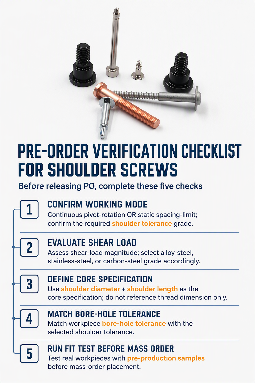
Pre‑order validation checklist for shoulder screws
Complete these checks before releasing bulk‑PO:
- Distinguish working mode: continuous pivot‑rotation OR static spacing‑stop; confirm required shoulder tolerance grade.
- Evaluate shear‑load magnitude and select matching material grade.
- Take shoulder diameter and shoulder length as core specification index, do not only reference thread dimension.
- Verify tolerance matching between shoulder shank and workpiece bore hole.
- Complete real‑workpiece assembly and movement test with pre‑production samples.
Closing summary
Performance of shoulder screws is determined by shoulder‑shank parameters, not thread specifications. A large share of field‑failure cases originate from overlooking shoulder‑related dimension and tolerance requirements. During mechanical‑design phase, clarify movement mode, load‑magnitude and service‑environment, and pass full dimensional requirements over to fastener suppliers to avoid preventable mass‑production troubles.
Post time: Sep-05-2026