
“2,000 pieces, 20 mm long, 8 mm OD, stainless, please quote.”
That sentence arrives in most spring inboxes several times a week. It is not a careless enquiry. It is an unfinished one. Nothing in it says what force the assembly needs, and without a force there is no wire diameter, no coil count, and no way to tell whether the part will bottom out halfway through its travel.
The geometry is easy to state because it is visible. The force is harder because it only exists once the mechanism is assembled and someone pushes it. So the enquiry stops at the visible half.
Most of this article is about the other half, in the order a designer has to resolve it.
Load at two heights, not at one
A single force at a single height describes a point. A spring is a line. Two points define it, and two points are enough to calculate everything else.
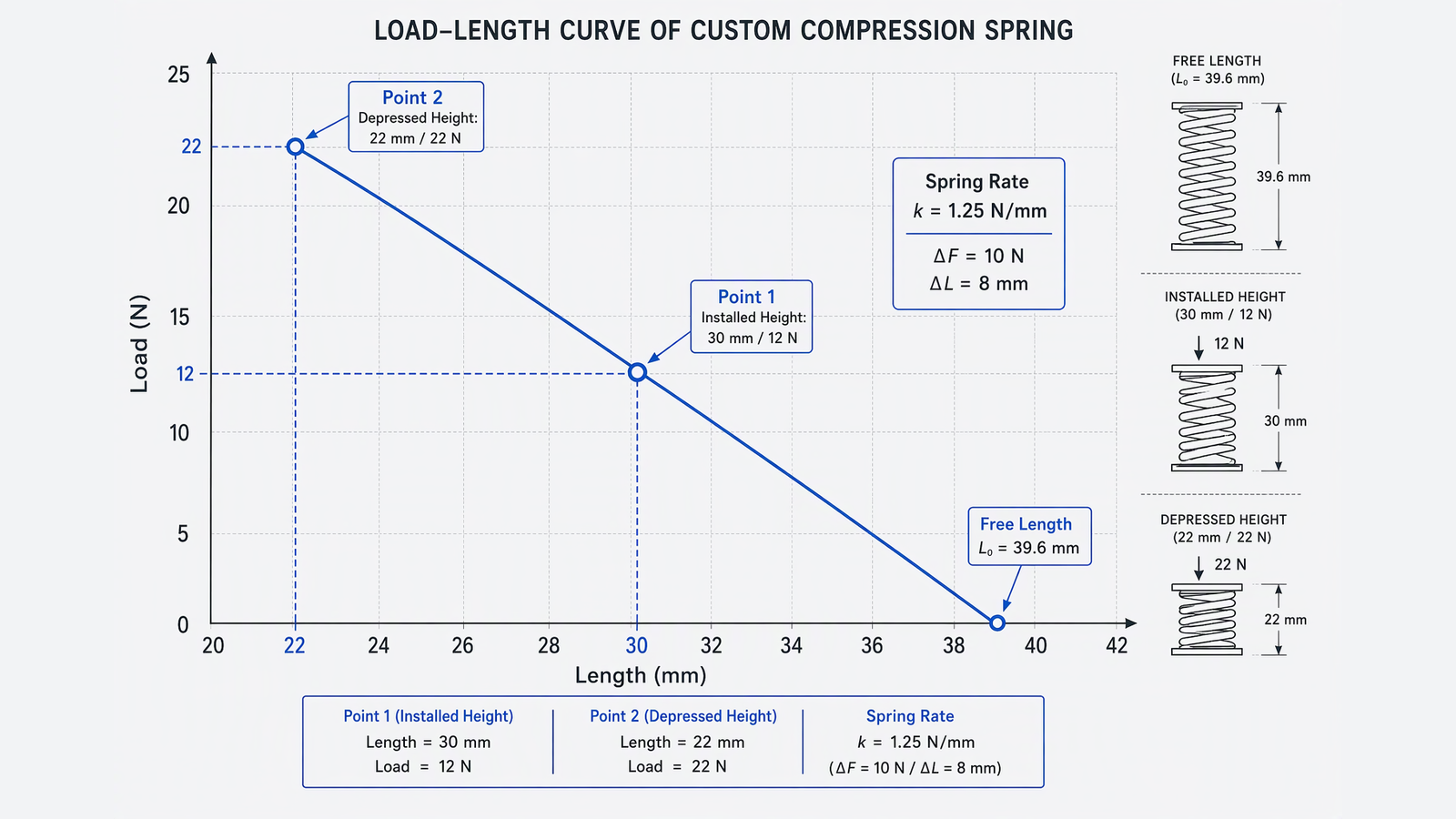
Take a switch actuator: the spring should give 12 N at an installed height of 30 mm, and 22 N when the plunger is fully depressed at 22 mm. The rate is the slope between them.
k = (22 − 12) N ÷ (30 − 22) mm = 1.25 N/mm
From that, the free length falls out: the spring must be compressed by 12 ÷ 1.25 = 9.6 mm to reach the installed height, so the free length is 30 + 9.6 = 39.6 mm. Check it at the second point: 39.6 − 22 = 17.6 mm of deflection, times 1.25, gives 22 N. The numbers close.
This is the whole calculation, and it is why two load points are worth more than a paragraph of description. If the spring is installed with no preload at all, one force and the free length will do, because the second point is zero. If it is installed with preload — which is most of the time, since a loose spring rattles — you need both.
The rate is an output, not something you choose
Buyers often ask for “about 1 N/mm” as if rate were a stock attribute. Rate is what the geometry produces:
k = G·d⁴ ÷ (8·D³·N)
where d is wire diameter, D is mean coil diameter, N is the number of active coils and G is the shear modulus of the material. The exponents are what matter in practice. Wire diameter sits on the fourth power, so a change from 0.50 mm to 0.60 mm — 20% thicker — raises the rate by 107%. Mean diameter sits on the third power in the denominator: widen the coil from 6 mm to 7 mm and the rate falls by about 37%.
That is why “just make the wire a bit thicker” is not a small adjustment, and why a supplier who quotes from a one-line enquiry is guessing. Two designers can produce the same 1.25 N/mm from very different wire: 0.5 mm wire on 6 mm mean diameter needs roughly 12 active coils, while 0.7 mm wire needs about 48. The second spring is stiffer in ways that do not appear in the rate at all — higher stress per unit deflection, a taller solid height, more material.
Rate tolerance and load tolerance can contradict each other
Commercial springs are commonly quoted to ±10% on rate, sometimes ±5%. That tolerance is almost never what the assembly actually feels. What it feels is the force at the installed height.
These are not the same requirement, and specifying both tightly can produce a part that cannot be made. A spring with rate 10% low can still deliver the correct installed load if the free length is adjusted to compensate; a spring with the correct rate can still miss the installed load if the free length tolerance is loose. Choose the one the mechanism depends on, and give the other room.
For a switch or a latch, that is usually the load at the working height, with a stated tolerance such as ±8%. For a spring that only has to hold a cover closed, rate is irrelevant and installed load is everything.
The envelope is a pair of diameters, not one
A drawing that says “OD 8 mm” leaves the assembly to chance, because the housing bore and the spring OD both have tolerances and they stack. An 8.00 mm spring in an 8.05 mm bore is fine; an 8.10 mm spring at the top of its tolerance in an 8.04 mm bore at the bottom of its is an interference fit that nobody designed.
Ask for the bore and the rod, not just the spring. If the spring runs on a guide rod, the minimum inside diameter matters more than the nominal, because a spring that grips the rod cannot compress freely and will wear the rod. If the spring sits in a blind bore, the corner radius at the bottom of the bore matters as well: a square-ended spring will not seat in a radiused pocket.
Slenderness deserves a mention here. A spring whose free length is more than roughly two and a half times its mean diameter will buckle before it reaches solid height unless it is guided by a rod or a bore. The drawing should say which.
Solid height is a stack of wire tolerances
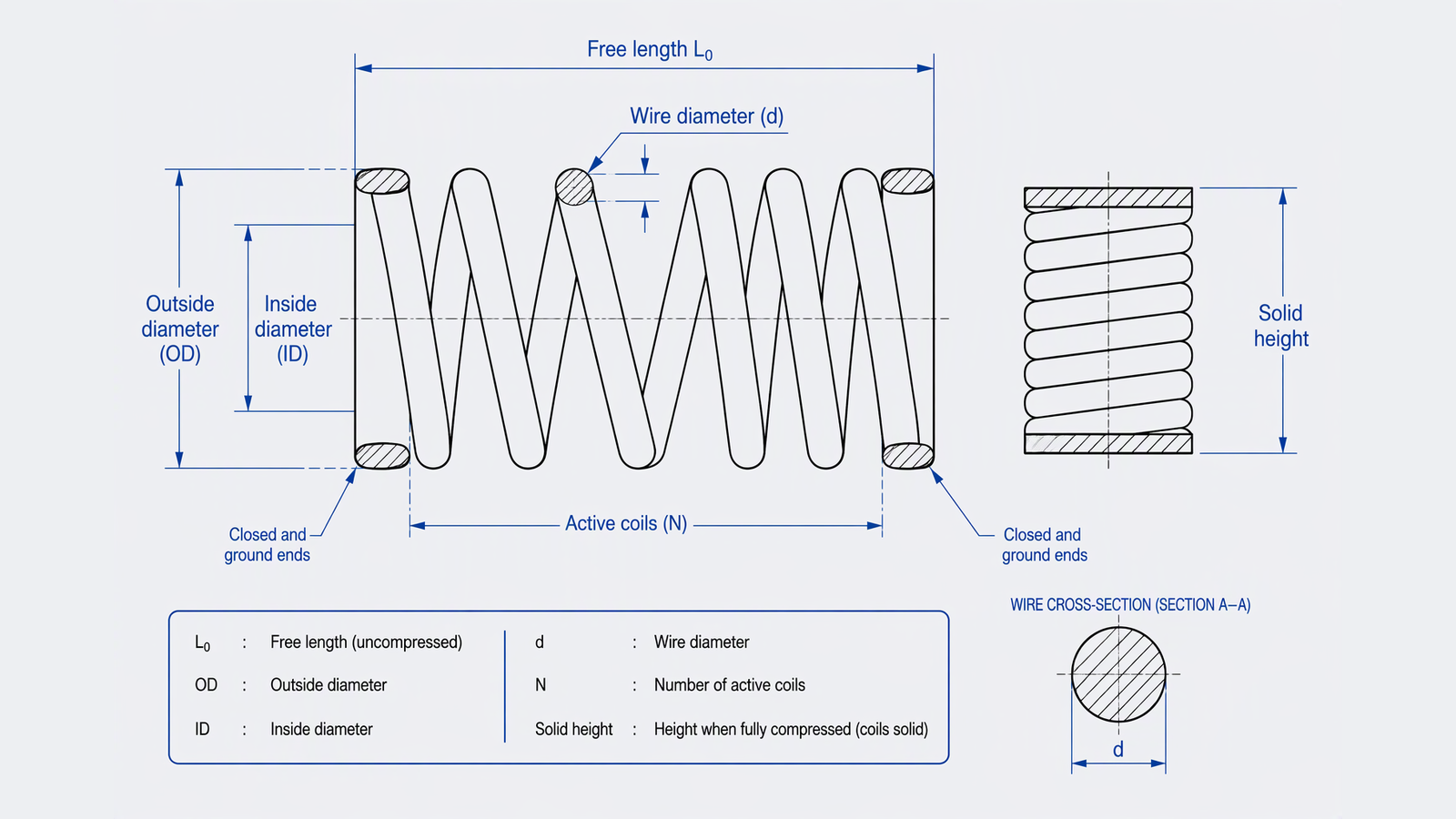
Solid height is the length with every coil touching. For a spring with closed ends it is approximately the total number of coils multiplied by the wire diameter.
The number most drawings miss is the tolerance. Wire diameter is not exact; a ±0.02 mm band on 0.50 mm wire across 12 total coils moves solid height by 0.24 mm. On a spring with 40 coils, the same band moves it by 0.8 mm — enough to eat the travel margin on a short-stroke mechanism.
Two things belong on the drawing: the maximum working compression, and whether coil contact must be avoided in normal operation. As a working rule, many designs keep the fully compressed position at least 10% above solid height, and more when the spring cycles hard. A spring that reaches solid height does not simply stop; the coils hammer each other, stress rises sharply at the end coils, and the free length starts to shorten.
Ends decide seating, squareness and cost
Four end conditions cover most of what gets ordered: open, open and ground, closed, closed and ground. The difference is not cosmetic.
Open ends are the cheapest to wind and the least square. They work when the spring bears on a shaped seat that can accommodate a tilted end coil. Closed ends add a dead coil at each end that lies flatter against a mating face. Closed and ground ends are machined square after coiling, which gives the best seating and the lowest solid height for a given coil count, at the cost of an extra operation and some scrap.
The question to answer is not which end looks tidy but where the force goes. A spring standing upright in a bore needs square ends or it will lean and rub. A spring compressed against a stamped bracket with a drawn edge needs enough end bearing area that the coil does not walk. If the assembly has a spring pocket with a chamfer, an open end may seat better than a ground one.
Material changes the rate, not just the corrosion resistance
The common assumption is that stainless is carbon steel with better corrosion resistance. It is not. Austenitic stainless has a shear modulus of roughly 69 GPa against roughly 79 GPa for carbon spring wire, so the same geometry in 302 or 304 delivers about 13% less force. A design copied from a carbon steel spring and re-specified in stainless will come in soft, and the usual reaction — add coils — changes solid height and stress.
Grade selection follows the duty. Music wire (ASTM A228) gives the highest tensile strength in small diameters and is the default for light, fast-acting parts. Oil-tempered wire (A229) suits larger diameters and general mechanical use. Chrome-silicon (A401) is the choice where fatigue life matters or where the spring runs warm. Austenitic stainless 302 and 304 cover outdoor and washdown exposure; 316 goes further on chlorides and chemical contact. Phosphor bronze appears where a non-magnetic or conductive spring is needed.
If the environment is the only reason for changing material, say so on the enquiry. There is often a finish that solves the corrosion problem without disturbing the rate.
Cycles, set removal and the free length nobody measures
A spring that is compressed once at assembly and never moves again is a different object from one that cycles 10 million times in a pump. The first is limited by yielding, the second by fatigue. Fatigue design keeps the working stress well below the material’s torsional limit and, where the cycle count is high, adds shot peening to put the surface into compression.
There is a second effect that surprises buyers. Newly coiled springs lose a little free length in service as the material settles. Manufacturers counter this by presetting — compressing the spring past solid height once so the coils take a permanent set under control, in the factory rather than in the customer’s mechanism. A preset spring arrives with a stable free length, and slightly shorter than the calculated one.
If free length is a controlled dimension in your assembly — and on a spring that sets the preload of a bearing or a seal, it usually is — the preset step has to be agreed before the first article, not discovered at incoming inspection.
Finish, and what it does to the fit
Plating and coating add thickness to the wire, which grows the outside diameter and shrinks the inside diameter by roughly twice the coating thickness. On a spring with a tight bore clearance that is enough to matter. Coating on a spring also cracks at the inside of the coil where strain is highest, so a decorative finish can fail first exactly where it is least visible.
For high-strength wire above roughly 1,000 MPa, electroplating brings a hydrogen embrittlement risk that has to be managed with a bake after plating, and thin wire is the least forgiving. Stainless springs are normally passivated rather than plated, which avoids the problem entirely.
What the same enquiry looks like when it is finished
Returning to the opening sentence, here is the version a spring designer can work with:
Application: switch actuator, 2,000 pcs/year, 30 mm installed height, 22 mm at full travel.
Load: 12 N ±8% at 30 mm; 22 N ±8% at 22 mm.
Envelope: housing bore 8.20 mm +0.05/0; guide rod 4.00 mm −0.02/0; pocket depth 41 mm.
Ends: closed and ground, both ends bearing on flat faces.
Material: stainless 304, indoor, no chemical exposure, −10 to 60 °C.
Life: 200,000 cycles, no coil contact in normal operation.
Acceptance: load at both heights, free length, solid height, squareness, OD, wire diameter; material certificate with the lot.
Nothing in that list requires a spring engineer to guess. The rate, the wire diameter and the coil count are all consequences, and the supplier can propose two or three geometries that meet the same envelope at different cost.
After the enquiry leaves your desk
The first reply should be a proposed geometry with its calculated rate, stress at both working points and solid height — not a price on its own. A quote without those numbers is a guess with a number attached.
The sample stage is where the assumptions get tested. Load should be checked at both stated heights rather than at one, free length measured after preset, and solid height verified against the drawing limit. If the sample is right at the first point and drifting at the second, the rate is off and the coil count needs revisiting, not the tolerance.
YH quotes compression springs alongside the stamped brackets and turned parts that usually sit around them, which matters when a spring seat is part of the same assembly drawing. The group has been making custom hardware since 1998 across two plants in Dongguan and Lechang, works to ISO 9001, ISO 14001 and IATF 16949, and runs hardness, tensile, salt spray and hydrogen embrittlement checks in its own laboratory, so material and finish questions can be settled before the parts ship rather than after.
FAQ
Is free length enough to specify a compression spring?
No. Free length only describes the spring at rest. It says nothing about the force at the height where the part is installed, and that force is what the mechanism actually uses.
Should I give the spring rate or the working loads?
Give the working loads at the heights you can measure in the assembly. Rate is derived from them. If you already have a rate and a free length from an existing design, give both and say which one is fixed, because the two cannot always be held at once.
Do I need to specify the number of active coils?
Only if the coil count is fixed by an existing spring, a patent or a supplier agreement. Otherwise active coils are an output of the design, and fixing them removes the supplier’s freedom to hit your load in the space you have.
How much space should I leave above solid height?
Most designs keep at least 10% of the compressed length as margin, and more for high-cycle or high-stress applications. The number that matters is the maximum compression the mechanism can physically impose, including over-travel during assembly and misuse.
Can you work from a sample instead of a drawing?
A sample gives dimensions, wire diameter and end style directly, and it is often the fastest route for a replacement part. It does not give the load the assembly needs, so send the sample together with the two working heights and the loads, or with the mechanism it sits in.
Click Here To Get Wholesale Quotation | Free SamplesPost time: Nov-16-2026