
“Deburr all edges” is not a specification. It is a wish. A supplier can meet it and still ship brackets that jam in your assembly, because the note says nothing about which edge matters, which face the burr may sit on, or how much burr is too much.
Three things have to be on the sheet instead: a named burr side, a measurable limit on the edges that actually function, and a clear statement of whether a secondary deburring operation is permitted. Everything else about edge quality follows from those three.
What a punched edge really is
A sheared edge is not a clean cut. It carries four zones: a rollover at the top where the material bends before it separates, a burnished band where the punch polishes through, a rougher fracture zone, and the burr at the exit side.
The burr height is set by punch-to-die clearance, tool sharpness and how many strokes the tool has run since its last grind. That last variable is the one buyers forget. A die cutting cleanly at 50,000 strokes will throw a noticeably taller burr at 400,000 on the same coil, at the same settings, with no change to the drawing. This is why a burr limit without a sampling rule is half a requirement. The part that passes first article is not automatically the part you receive in month six.
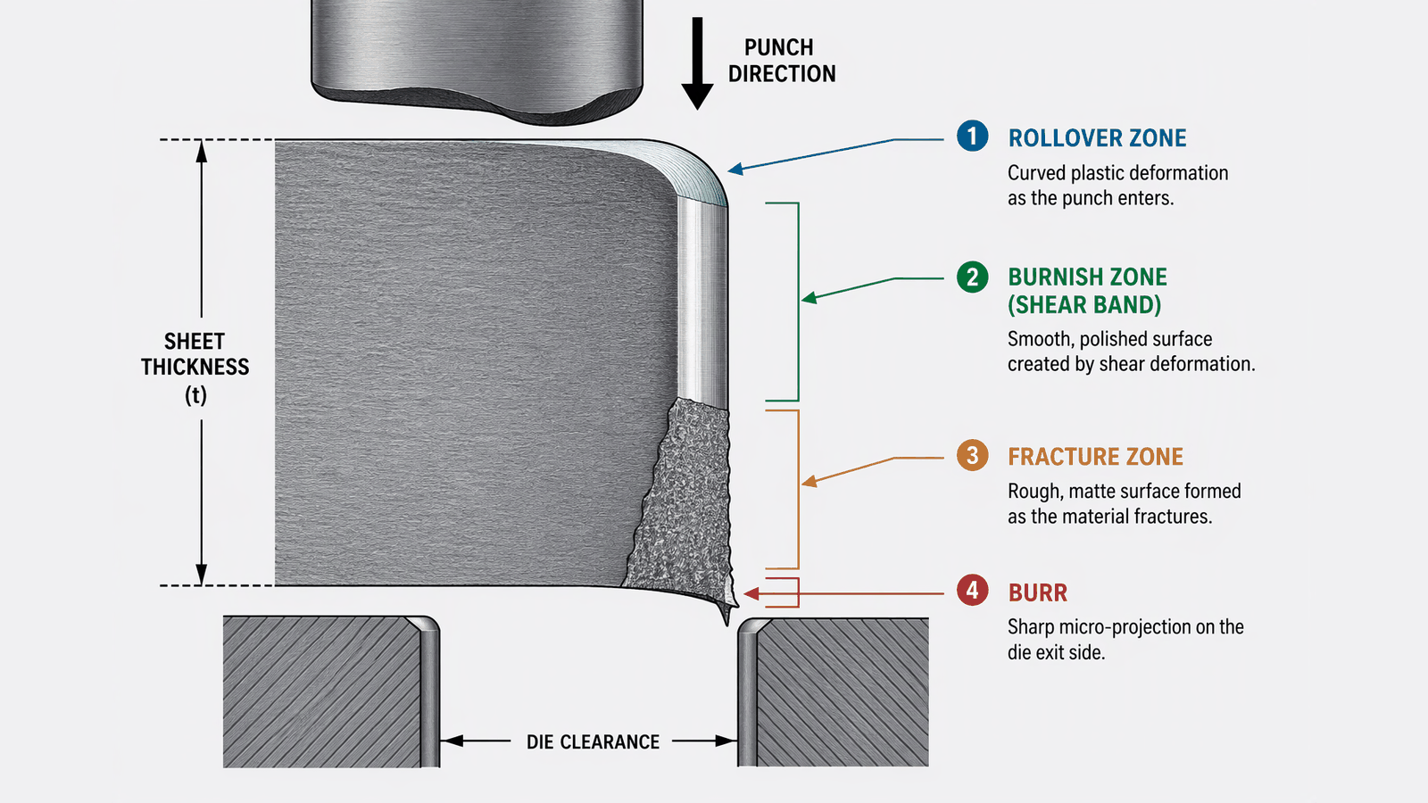
One bracket, five edges, five different answers
Consider a spring clip bracket of the kind used to hold a screen or a control board inside an enclosure. One flat blank, a formed clip leg, a locating hole, a raised contact point, a tab the operator pushes, and an outer edge that the customer sees.
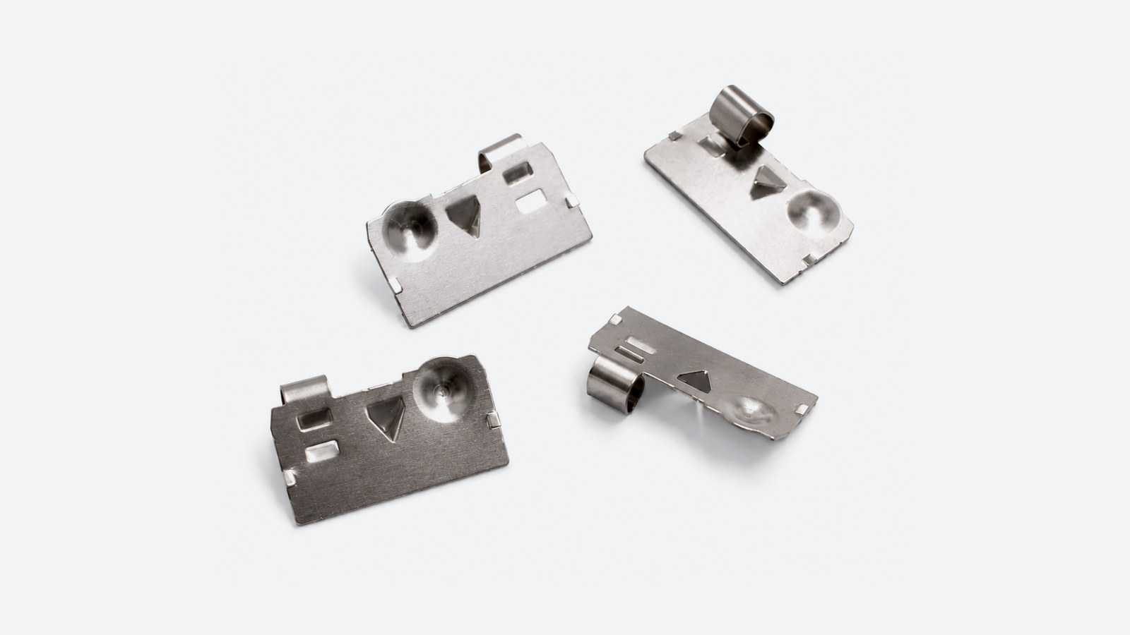
Every one of those edges needs a different answer, and the answers conflict.
The clip leg slides into a slot in the housing. Clearance might be five hundredths of a millimetre. A burr on the outer face of that leg adds thickness exactly where the clearance is tightest, so the leg either will not enter or enters by shaving the housing. On the inner face the same burr is harmless. Same edge, opposite conclusion, and the drawing has to say which face is which.
The locating hole takes a pin. A burr left inside the hole reduces the effective diameter, and a pin designed with 0.05 mm of clearance suddenly presses. The burr side here is decided by which face the punch enters from, which is a tooling decision the drawing can either control or leave to chance.
The raised contact point has to sit at a defined height above the base. Burr at the edge of that formed feature can lift the contact plane or drop it, and the stack height of the whole assembly moves by a couple of hundredths. Nobody measures it until the housing does not close.
The tab the operator pushes is a handling question. A sharp edge there cuts gloves and stops a line, but the fix is an edge break, not a full deburring operation.
The visible outer edge is appearance only. It matters, and it is the cheapest of the five to satisfy.
A single “burr-free” note collapses all five into one instruction. The shop then either applies the most expensive interpretation across the whole part or picks the one it thinks you meant. Both outcomes cost somebody money.
Four words that are not interchangeable
Most edge arguments come from using one word for four different requirements. Split them and the drawing becomes quotable.
| Requirement | What it controls | Wording that works |
|---|---|---|
| Burr direction | Which face may carry the burr | Burr permitted on face B only; face A to be burr-free |
| Burr height | How large the burr may be, per edge | Max burr 0.05 mm on the clip leg outer edge, both ends |
| Edge condition | Whether an edge may stay sharp or needs a break | Edge break R0.2 to R0.3 on the operator tab |
| Deburring | Whether a secondary operation is required | Deburring not permitted on the locating hole |
Two traps sit inside that table. Specifying deburring does not define the resulting edge radius; a tumbling operation will produce whatever radius the media and time produce. And specifying an edge radius does not guarantee that the hole diameter or the clip height survives the operation. If the radius is functional, it needs its own tolerance and its own inspection.
Direction is meaningless without an orientation
“Burr down” is the most common note on stamped drawings and the least reliable. Down relative to what? A flat bracket can sit in the fixture either way up, and a progressive die can feed the strip from either end.
Anchor the burr side to something stable. A datum face. A named view. The side that contacts the housing. Then add the bend direction, because forming flips the relationship: a burr that sat on the outside of the blank ends up on the inside of the formed leg, and anyone reading the flat pattern will get it backwards.
We have seen a 200,000-piece order held at incoming inspection over exactly this. The parts matched the flat drawing. They did not match the assembly.
A burr limit needs a method attached
“Max burr 0.05 mm” on 0.6 mm sheet is about eight percent of material thickness. That is measurable, but only with the right instrument: a profile projector or a toolmaker’s microscope at magnification, checked against a cross-section. It is not measurable with a fingernail, and it is not measurable by eye at arm’s length.
So the drawing, or the inspection plan behind it, should state three things: which edge segment gets measured, with what instrument, and on how many parts per lot. Without those, the inspector measures the easiest edge and signs the report. The difficult edge, the one that jams the assembly, never gets looked at.
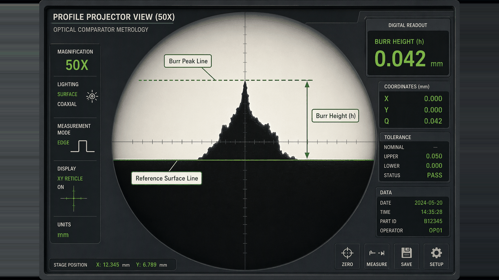
There is a practical shortcut worth agreeing early. Photograph the first article at the functional edges, at magnification, and attach the images to the approval. A photograph settles more burr disputes than a tolerance value, because both sides can see the same thing.
Where ISO 13715 helps, and where it stops
ISO 13715 provides symbols for edges of undefined shape and rules for dimensioning them. On a drawing full of non-critical cut edges, it is a clean way to say “general condition, no sharp edge” once instead of fifty times.
It cannot answer the question that matters on a clip bracket, which is which face may carry the burr. A general edge notation describes a condition; it does not describe a direction, and it does not set a limit at a specific functional edge. Use it for the background, and keep the functional callouts specific.
Some burrs are decided before the tool is cut
Burr control is usually discussed as a finishing problem. In practice the expensive decisions are geometry decisions.
Hole-to-edge distance is the clearest example. A hole placed close to the blank edge leaves a thin web. That web tears, distorts and throws a heavier burr than the same hole placed a few millimetres further in. The fix costs nothing at design stage and a die modification later.
Narrow slots behave the same way. A slot narrower than the sheet thickness is hard to shear cleanly, and the punch is fragile. Widening it slightly, or moving it away from a bend, changes both burr and tool life.
Bend lines and rolling direction matter on anything formed. A bend running along the rolling direction cracks sooner than a bend across it, especially on harder tempers and on aluminium. If the part needs a tight bend radius, the grain direction belongs on the drawing, not in a conversation.
Sharp internal corners concentrate wear on one point of the punch. That corner throws the tallest burr on the part and is the first place the tool fails. A small radius there costs a drawing revision before tooling and a die insert after it.
Deburring is a process choice with side effects
Tumbling and vibratory finishing round every edge the media reaches, which includes the edges you wanted left alone. A clip tip that has to present a defined contact line loses it. A locating hole can grow by a few hundredths on thin sheet. Neither is a defect in the finishing shop’s terms, and both can fail your assembly.
Sequence matters too. Deburr before plating, because plating builds on edges and a burr tip carries a thin, poorly adherent coating that breaks away in service. On hardened spring steel, any plating step brings hydrogen embrittlement into the conversation, and the bake that follows plating is a requirement to state rather than assume.
The honest position is that deburring should be specified per edge, not per part. On most brackets two or three edges need attention and the rest are fine as sheared. Telling the shop which is which usually reduces the price rather than raising it.
What to inspect, and when
First article is where the argument should end. Check the functional edges, the burr side relative to the datum, any stated height limit, and the geometry of holes and formed features after finishing, since deburring and plating both move dimensions.
After that, sampling frequency should follow tool life rather than calendar. Burr grows with stroke count, so the sensible checkpoints are after a regrind, after a tool repair, and at an agreed interval within the run. A lot sampled at stroke 10,000 tells you very little about stroke 300,000.
The package that gets a useful quote
Two files, plus a short note. A 2D drawing with the edge callouts and a 3D model for the formed geometry. Then the things that never fit a title block: material grade and temper, thickness and its tolerance, grain direction where bends are tight, which edges are functional, which face may carry the burr, the limit per edge, whether deburring is allowed, the finish and whether it goes on before or after any edge work, annual quantity next to prototype quantity, and the inspection document you expect with the shipment.
That last item changes the price more than buyers expect, and it is cheaper to settle before the tool is cut than after the first lot.
Stamping at our own presses runs from 10 to 300 tonnes, with small-feature tolerances quoted to ±0.02 mm where the part allows it, and first articles checked on CMM and optical comparator against the drawing before a run is released. All of which only helps if the drawing states what the edge has to do.
FAQ
Are burrs on stamped parts a defect?
Not automatically. A burr is the normal exit-side result of shearing. It becomes a defect when it exceeds a stated limit, sits on a face where it interferes, or is left on a handling edge. The drawing decides which of those applies.
How do I show burr direction without ambiguity?
Reference it to a datum face or a named view, then add the bend direction so the formed part and the flat pattern agree. Notes like “burr down” or “burr on the back” fail as soon as the part can be viewed or installed either way up.
Does “burr-free” mean every edge is rounded?
No. It usually means no burr above a limit, which is a different requirement from an edge radius. If a specific radius is needed for function, dimension it separately and inspect it separately.
Should every stamped part be deburred?
No. Deburring should follow function. Blanket tumbling adds cost, rounds edges that may need to stay defined, and can move small hole sizes on thin material. Specify it edge by edge.
Can burr height be held over a long production run?
It drifts with tool wear. A limit is only meaningful with a sampling plan tied to stroke count and tool maintenance, and with an agreed measurement method. Set the limit, the instrument and the frequency together.
An edge note takes one line on a drawing. The argument it prevents takes a week, a rejected lot, and a conversation about who pays for the sorting. That trade is worth making at the design stage, when a radius is still free to change.
Click Here To Get Wholesale Quotation | Free SamplesPost time: Nov-15-2026